Copyright © Thomas Fetter
2014-2016
Home>
Electronics>
The hardware is just part of the solution.  There is significant software required to calibrate and convert the output of the sensors into the desired parameters of angle and position.  Much of the required software has been created by the hobbyist UAV community.  The xxx website is the center of this community.  Software is available at this site, on the Sparkfun site, and on the Mongoose site.  The Mongoose site has combined all the required software.
Starting with the CKdevices software for Mongoose, I am modifying it so that it will work for my rocket orientation application.  Here is the Arduino Software for the Mongoose Rocket Project.


IMU Project
IMU Project >
To test my flight dynamics model, I need to measure 3 degrees of rotation and three degrees of relative position of the rocket.  There are many low cost IC sensors now available that measure angular rotation rate (rate gyros), acceleration, and magnetic field.  Combined with an Arduino processor, these open up the possibility of creating a sensor to measure these parameters.
 
This is a project that I have just started.  I will keep this site updated as I progress on this project.  Note: after starting this project, RAF Research introduced the
AL-016 High Speed Data Logger that provides accelerometer and rate gyroscope data.  See Flight Visualization for details.
 
A number of companies provide breakout boards with the IC's already mounted, which makes using the surface mount IC's much easier.  Sparkfun and Adafruit are examples of two of these companies.  Sparkfun, in particular, has a wide range of the required sensors from a ranger of the major IC sensor companies.  The accelerometers come in different sensitivities.  It's important to select a sensor that can handle the highest expected acceleration of the rocket (in the 10's of gee's). Sparkfun has boards that combine the 3-axis rate gyro, 3-axis accelerometer, and 3-axis magnetic field sensor on a single board.  Such boards are called Inertial Measurement Units (IMU's). But not all of these boards have sensor that have the right ranges of rocket use.  


A smaller site, ckdevices, has created a design that has appropriate sensors, as well as a barometric sensor - perfect for rocket use.  The board is called the Mongoose.  It was actually created for the hobbyist UAV market.  It also integrates the Atmel Atmega 328P processor on the same board, and supports the Arduino development environment, making this a single board IMU solution that would work for this application.

Note - as of this update, it appears that the Mongoose board is not currently available from ckdevices.

Here are links to the datasheets for the sessors used on the Mongoose board:

Honeywell          HMC5883L         3-Axis Digital Compas IC

Analog Devices   ADXL345            Digital Accelerometer 3-Axis +-16g

Bosch                BMP085             Digital Pressure Sensor

InvenSense         ITG-3200            3-Axis MEMS Gyroscope


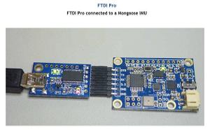
An FTDI Pro board, also available from ckdevices, is required to interface the Mongoose board to your computer via USB for programming.
To control and read the sensors, a processor and programming environment is required.  The Arduino is a processor and open standard development environment based on the Atmel processor.  Arduino is among the most popular of hobbyist processor board and integrated development environments (IDE) that is easy to use for hobbyists. The official Arduio web site has all the information and downloads necessary to set up the Arduino IDE on you PC.  All programming of the Ardunio is done from the Arduino IDE. 

The Arduino has plenty of power and speed for this application, which makes it an excellent choice. 

O'Reilly publishers has an excellent book on Arduino, the Arduino Cookbook by Michael Margolis

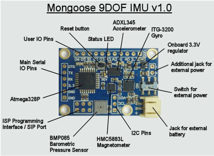
The software that has been developed for  the UAV control will not work as is for measuring the position of a rocket in flight.  For example, the accelerometer is used as a part of the system calibration.  The 1 gee gravity field is sensed and is assumed to be "down".  This does not hold for a rocket under high acceleration.  So a lot of work is required to modify the software to work for this application.

The rate gyros can probably be made to work for this application, but it is not clear that the accelerometers can be used to get incremental position data.  Theoretically, position is just a double integration of the acceleration data, but any small offset, or error, in the accelerometer reading "blows up" after two integration and swamps the actual change in location of the rocket.  The error grows over time, so, the fact that the position is only being measured over 10's of seconds means this may be doable.  But the presence of a 1 gee field that must be subtracted out of the data may make this impossible.   A very small error in determining the direction of the gravity field makes the data unusable.

 This is an ongoing project. I will post updates as I progress.

Once the IMU data has been recorded by the Mongoose, it will be necessary to play back the data to visualize the position of the rocket during its flight.  For this, a separate program is used on the PC that reads in the data from the Mongoose and shows the orientation of the rocket using a graphical representation. 

To do this, I wrote a version of the Python script that I use for visualizing my flight simulation model that reads the Mongoose in realtime.  Here is a recording of the Python flight position visualization software hooked directly to the Mongoose.  The Mongoose unit is being rotated about its three axes by hand.  Note that the z spin axis is allowed to rotate independently of the x and y axes as the convention for modeling the orientation of a rocket with its single long axis.

Click here to see the video.
Home

Spreadsheets
& Calculators


Flight Theory

Flight Data Analysis

Electronics

Construction
Tools & Techniques


Rocket Projects

Links

About

History